---
title: "How to Read a Feature Control Frame"
description: "A feature control frame is read left to right. Here's what each compartment means, from the geometric symbol to the datum references, per ASME Y14.5-2018."
url: "https://gndctl.com/insights-library/how-to-read-a-feature-control-frame"
author: "GroundControl Editorial Team"
published: "2026-09-30"
updated: "2026-10-02"
insights_url: "https://gndctl.com/resources/how-to-read-a-feature-control-frame"
category: "GD&T"
tags: ["GD&T","ASME Y14.5","Feature Control Frame","AS9102","Inspection","Aerospace"]
---

# How to Read a Feature Control Frame


> Full Markdown index: https://gndctl.com/llms.txt

> Human-readable version: https://gndctl.com/resources/how-to-read-a-feature-control-frame


## Key takeaways

- Read a feature control frame left to right: geometric characteristic, tolerance zone (including Ø and modifiers), then datum references in primary–secondary–tertiary order.
- Follow the leader arrow first—it determines whether the control applies to a surface or a feature of size and what the tolerance zone constrains.
- Tolerance values are total zone widths, not ± dimensions; MMC in the tolerance compartment allows bonus tolerance equal to the feature’s departure from MMC.
- ASME Y14.5-2018 defines twelve geometric characteristic symbols; confusing datum modifiers, RFS/RMB defaults, or datum order changes setup and results on real parts.
- On AS9102 Form 3, record the full frame—symbols, modifiers, and datum sequence—not the numeric tolerance alone.

## How to Read a Feature Control Frame

A feature control frame is the boxed callout on a drawing that applies a geometric tolerance to a feature. You read it left to right, and each compartment answers a different question: what is being controlled, how much variation is allowed, what shape that allowance takes, and relative to what.

Misreading even one compartment can mean measuring the wrong thing, correctly. Some examples include writing the wrong method into the inspection plan, buying a fixture you did not need, or rejecting a part that was good.

## What is a feature control frame?

A feature control frame is a rectangular box on an engineering drawing that specifies a geometric tolerance. It is how GD&T gets written down. Every frame has at least two compartments, but most have three to five.

For a broader introduction to the language the frame is written in, see [Understanding GD&T: A Practical Guide for Aerospace Quality Teams](https://gndctl.com/resources/understanding-gd-t-a-practical-guide-for-aerospace-quality-teams).

## The parts of a feature control frame

:::html
<figure class="fcf-parts-figure">
  <img
    src="/images/insights/how-to-read-feature-control-frame-figure-1.png"
    alt="Figure 1"
    loading="lazy"
  />
</figure>
:::

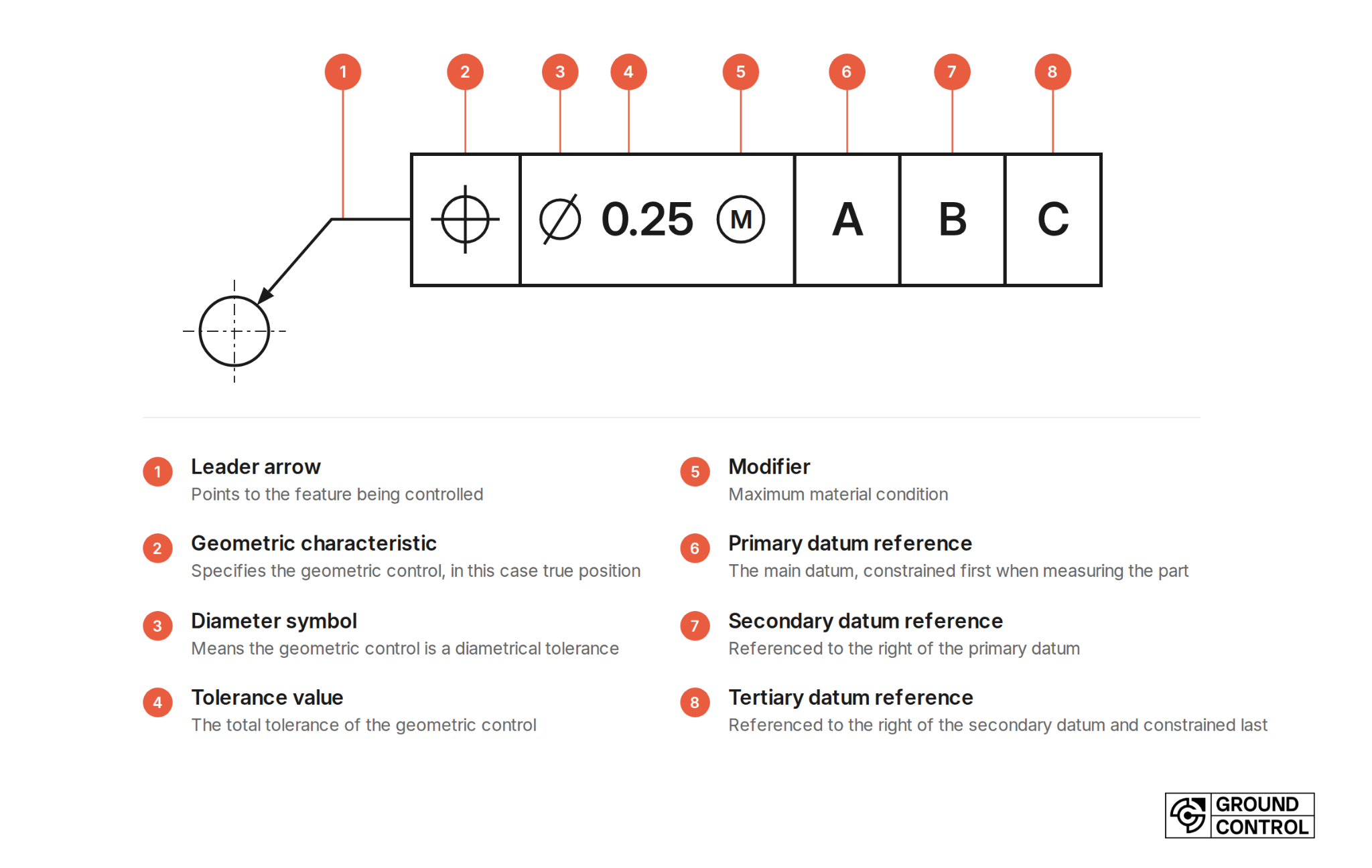
1. **Leader arrow.** Points to the feature being controlled. For example, if it points to a surface, then that surface is controlled by GD&T. However, the leader arrow is optional and may not be present on all drawings.
2. **Geometric characteristic.** The first compartment names the geometric control. Read more about GD&T [here](https://gndctl.com/resources/understanding-gd-t-a-practical-guide-for-aerospace-quality-teams).
3. **Tolerance value.** The total tolerance of the geometric control, based on the drawing standard.
4. **Modifier.** An optional symbol that changes how the tolerance applies; if no modifier follows a datum feature size, the datum feature applies regardless of material boundary.
5. **Diameter symbol.** If the geometric control is a diametrical tolerance, then the diameter symbol (Ø) will be in front of the tolerance value. If not, there's no symbol.
6. **Datum references.** This section includes a primary, secondary, and/or tertiary datum reference. The letter corresponds to a feature on the part that will be marked with the same letter. The primary datum is usually in 3 places to fix 3 degrees of freedom. A secondary datum will be to the right of the primary, and a tertiary datum will be to the right of a secondary datum.

## How to read a feature control frame, step by step

1. **Follow the leader arrow.** Decide whether the control lands on a surface or on a feature of size. That sets what the tolerance zone constrains.
2. **Read the geometric characteristic symbol.** It tells you the category of control and whether datums are required, optional, or not permitted.
3. **Read the diameter symbol.** Diameter symbol means a cylinder. Spherical diameter means a sphere. Nothing means two parallel planes.
4. **Read the tolerance value as a total zone width,** not a plus or minus.
5. **Read the modifier, if there is one.** No modifier in the tolerance compartment means the control applies regardless of feature size, with no bonus tolerance.
6. **Read the datum references in order.** First listed is primary, second is secondary, third is tertiary. This sequence is your inspection setup.

## A worked example

:::html
<figure class="fcf-callout-figure">
  <img
    src="/images/insights/how-to-read-feature-control-frame-callout.png"
    alt=""
    loading="lazy"
  />
</figure>
:::

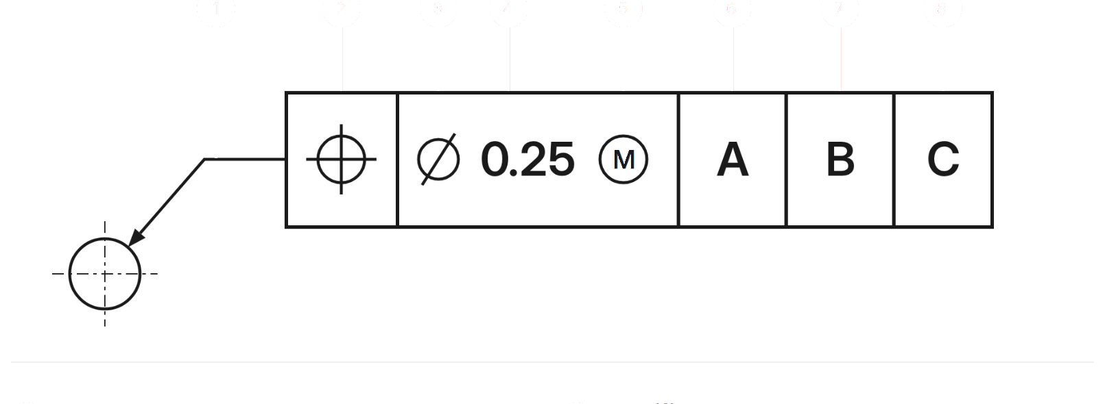
Take the callout above, applied to a hole. Read out loud, it says:

The axis of this hole must lie within a **cylindrical zone 0.25 in diameter**, located at true position by the basic dimensions on the drawing. That zone applies when the hole is at its **maximum material condition**, which for a hole is its smallest allowed size. As the hole is produced larger, **bonus tolerance** becomes available, equal to the amount it departs from MMC. The zone is established relative to **datum A first**, then **datum B**, then **datum C**.

A hole produced 0.03 larger than MMC earns 0.03 of additional position tolerance, for a total zone of 0.28. The bonus is equal to the departure, not merely proportional to it.

For inspection, the datum sequence is your setup instruction. Datum A constrains the part first. Datum B constrains it next, and Datum C constrains what is left.

## The twelve geometric characteristic symbols

:::html
<div class="overflow-x-auto my-6">
<table class="fcf-characteristics-table w-full text-sm border-collapse border border-stone-200">
<thead>
<tr class="bg-stone-50 text-left">
<th class="border border-stone-200 px-4 py-3 font-semibold text-stone-900">Symbol</th>
<th class="border border-stone-200 px-4 py-3 font-semibold text-stone-900">Characteristic</th>
<th class="border border-stone-200 px-4 py-3 font-semibold text-stone-900">Applies to</th>
<th class="border border-stone-200 px-4 py-3 font-semibold text-stone-900">Datums</th>
<th class="border border-stone-200 px-4 py-3 font-semibold text-stone-900">Description</th>
<th class="border border-stone-200 px-4 py-3 font-semibold text-stone-900">Modifier applicable to datum feature</th>
</tr>
</thead>
<tbody class="text-stone-700">
<tr><td class="border border-stone-200 px-4 py-3">⏤</td><td class="border border-stone-200 px-4 py-3">Straightness</td><td class="border border-stone-200 px-4 py-3">Line element or derived median line</td><td class="border border-stone-200 px-4 py-3">Not permitted</td><td class="border border-stone-200 px-4 py-3">Used to describe how straight a given linear element can be.</td><td class="border border-stone-200 px-4 py-3">cannot be modified</td></tr>
<tr><td class="border border-stone-200 px-4 py-3">⏥</td><td class="border border-stone-200 px-4 py-3">Flatness</td><td class="border border-stone-200 px-4 py-3">Surface or derived median plane</td><td class="border border-stone-200 px-4 py-3">Not permitted</td><td class="border border-stone-200 px-4 py-3">Used to limit the maximum flatness error allowed for the specified surface.</td><td class="border border-stone-200 px-4 py-3">cannot be modified</td></tr>
<tr><td class="border border-stone-200 px-4 py-3">○</td><td class="border border-stone-200 px-4 py-3">Circularity</td><td class="border border-stone-200 px-4 py-3">Surface</td><td class="border border-stone-200 px-4 py-3">Not permitted</td><td class="border border-stone-200 px-4 py-3">Used to describe how close the chosen cross section needs to be to the specified circularity.</td><td class="border border-stone-200 px-4 py-3">cannot be modified</td></tr>
<tr><td class="border border-stone-200 px-4 py-3">⌭</td><td class="border border-stone-200 px-4 py-3">Cylindricity</td><td class="border border-stone-200 px-4 py-3">Surface</td><td class="border border-stone-200 px-4 py-3">Not permitted</td><td class="border border-stone-200 px-4 py-3">Describes a theoretical cylinder in which the overall form of the cylindrical feature is controlled.</td><td class="border border-stone-200 px-4 py-3">cannot be modified</td></tr>
<tr><td class="border border-stone-200 px-4 py-3">⌒</td><td class="border border-stone-200 px-4 py-3">Profile of a line</td><td class="border border-stone-200 px-4 py-3">Surface, 2D cross section</td><td class="border border-stone-200 px-4 py-3">Optional, required when located or oriented</td><td class="border border-stone-200 px-4 py-3">Describes a 2D tolerance zone across a line. The profile controls all points along the simple or complex line.</td><td class="border border-stone-200 px-4 py-3">cannot be modified</td></tr>
<tr><td class="border border-stone-200 px-4 py-3">⌓</td><td class="border border-stone-200 px-4 py-3">Profile of a surface</td><td class="border border-stone-200 px-4 py-3">Surface, 3D</td><td class="border border-stone-200 px-4 py-3">Optional, required when located or oriented</td><td class="border border-stone-200 px-4 py-3">Describes a 3D tolerance zone across any surface. The profile controls all points along the simple or complex surface.</td><td class="border border-stone-200 px-4 py-3">cannot be modified</td></tr>
<tr><td class="border border-stone-200 px-4 py-3">∠</td><td class="border border-stone-200 px-4 py-3">Angularity</td><td class="border border-stone-200 px-4 py-3">Surface, axis, or median plane</td><td class="border border-stone-200 px-4 py-3">Required</td><td class="border border-stone-200 px-4 py-3">Describes the specific orientation of a feature to another based on a referenced angle set as a datum.</td><td class="border border-stone-200 px-4 py-3 fcf-symbol-cell">Ⓜ</td></tr>
<tr><td class="border border-stone-200 px-4 py-3">⊥</td><td class="border border-stone-200 px-4 py-3">Perpendicularity</td><td class="border border-stone-200 px-4 py-3">Surface, axis, or median plane</td><td class="border border-stone-200 px-4 py-3">Required</td><td class="border border-stone-200 px-4 py-3">Used to control the orientation of a surface with respect to a specified datum at 90 degrees.</td><td class="border border-stone-200 px-4 py-3 fcf-symbol-cell">Ⓜ</td></tr>
<tr><td class="border border-stone-200 px-4 py-3">∥</td><td class="border border-stone-200 px-4 py-3">Parallelism</td><td class="border border-stone-200 px-4 py-3">Surface, axis, or median plane</td><td class="border border-stone-200 px-4 py-3">Required</td><td class="border border-stone-200 px-4 py-3">Used to control the orientation of a surface or axis with respect to a specified datum that is parallel to it.</td><td class="border border-stone-200 px-4 py-3 fcf-symbol-cell">Ⓜ</td></tr>
<tr><td class="border border-stone-200 px-4 py-3">⌖</td><td class="border border-stone-200 px-4 py-3">Position</td><td class="border border-stone-200 px-4 py-3">Feature of size</td><td class="border border-stone-200 px-4 py-3">Usually required</td><td class="border border-stone-200 px-4 py-3">Describes the total permissible variation that a feature can move from its true position. The position is given as coordinates defined by datums.</td><td class="border border-stone-200 px-4 py-3 fcf-symbol-cell">Ⓜ Ⓛ</td></tr>
<tr><td class="border border-stone-200 px-4 py-3">↗</td><td class="border border-stone-200 px-4 py-3">Circular runout</td><td class="border border-stone-200 px-4 py-3">Surface</td><td class="border border-stone-200 px-4 py-3">Required</td><td class="border border-stone-200 px-4 py-3">Used to control radial deviations of the specified cross sectional element of a circular feature. Taken with respect to the axis of rotation referenced by the specified datum.</td><td class="border border-stone-200 px-4 py-3">cannot be modified</td></tr>
<tr><td class="border border-stone-200 px-4 py-3">⌰</td><td class="border border-stone-200 px-4 py-3">Total runout</td><td class="border border-stone-200 px-4 py-3">Surface</td><td class="border border-stone-200 px-4 py-3">Required</td><td class="border border-stone-200 px-4 py-3">Used to control radial deviations of the specified cross sectional element of a cylindrical feature. Taken with respect to the axis of rotation referenced by the specified datum.</td><td class="border border-stone-200 px-4 py-3">cannot be modified</td></tr>
</tbody>
</table>
</div>
:::

## Modifiers

Modifiers in GD&T are symbols and letters that are added to a feature control frame to define tolerances, define material conditions, and control how a feature's size relates to the limits set by the constraints.

:::html
<div class="overflow-x-auto my-6">
<table class="fcf-modifiers-table w-full text-sm border-collapse border border-stone-200">
<thead>
<tr class="bg-stone-50 text-left">
<th class="border border-stone-200 px-4 py-3 font-semibold text-stone-900">Modifier</th>
<th class="border border-stone-200 px-4 py-3 font-semibold text-stone-900">Symbol</th>
<th class="border border-stone-200 px-4 py-3 font-semibold text-stone-900">Description</th>
</tr>
</thead>
<tbody class="text-stone-700">
<tr><td class="border border-stone-200 px-4 py-3">Least Material Condition</td><td class="border border-stone-200 px-4 py-3">Ⓛ</td><td class="border border-stone-200 px-4 py-3">Feature of size symbol that describes the condition of a feature or part where the least amount of material exists within the dimensional tolerance.</td></tr>
<tr><td class="border border-stone-200 px-4 py-3">Maximum Material Condition</td><td class="border border-stone-200 px-4 py-3">Ⓜ</td><td class="border border-stone-200 px-4 py-3">Feature of size symbol that describes the condition of a feature or part where the maximum amount of material exists within the dimensional tolerance.</td></tr>
<tr><td class="border border-stone-200 px-4 py-3">Projected Tolerance Zone</td><td class="border border-stone-200 px-4 py-3">Ⓟ</td><td class="border border-stone-200 px-4 py-3">Tolerance must be assessed beyond the surface extents of the feature.</td></tr>
<tr><td class="border border-stone-200 px-4 py-3">Free State</td><td class="border border-stone-200 px-4 py-3">Ⓕ</td><td class="border border-stone-200 px-4 py-3">Tolerance must be assessed in an unrestrained state. By default all dimensions are evaluated in a Free State unless otherwise specified.</td></tr>
<tr><td class="border border-stone-200 px-4 py-3">Tangent Plane</td><td class="border border-stone-200 px-4 py-3">Ⓣ</td><td class="border border-stone-200 px-4 py-3">Indicates that a specific control is applied to a theoretical tangent plane within the high points of an irregular surface rather than the elements of the surface themselves.</td></tr>
<tr><td class="border border-stone-200 px-4 py-3">Unequally Disposed Profile</td><td class="border border-stone-200 px-4 py-3">Ⓤ</td><td class="border border-stone-200 px-4 py-3">Used to apply unilateral or unequal tolerance zones to a profile.</td></tr>
</tbody>
</table>
</div>
:::

## Five common misreads

1. **Treating the tolerance value as bilateral.** It is a total zone. This one silently doubles the tolerance an inspector thinks they have.
2. **Ignoring datum precedence.** A, B, C is a setup sequence. Reordering it changes the result on a real part.
3. **Applying a datum modifier to the feature tolerance.** Circled M after a datum letter is a boundary condition on the datum, not a bonus on the feature.
4. **Assuming a bonus exists when no modifier is shown.** In the tolerance compartment, none means RFS and no bonus. In a datum compartment, none means RMB and no shift.
5. **Reading a composite lower segment as a location control.** It is orientation and feature-to-feature relationship only.

## Carrying the frame through to your FAI

Once the frame is read correctly it still has to survive the trip to the inspection report. On an AS9102 first article, every geometric callout becomes a ballooned characteristic with its own line on Form 3, and the requirement recorded there needs to reflect the whole frame, including modifiers and datum references, not just the tolerance value.

That is where reading errors become documented errors. A frame recorded as "0.25" without its diameter symbol, its material condition modifier, or its datum sequence is not the requirement the customer specified, and a reviewer checking it against the print will find the difference.

GroundControl's [FAI Generation software](https://gndctl.com/solutions/first-article-inspection-software) auto-balloons drawings and builds AS9102 Rev C Forms 1 through 3, with validation checks that flag revision mismatches and out-of-tolerance results before submission. GroundControl's [FAI Generation software](https://gndctl.com/solutions/first-article-inspection-software) reads GD&T symbols directly from the drawing, so a position symbol isn't recorded as a zero. For the mechanics of filling in the forms, see [How to Actually Fill Out an AS9102](https://gndctl.com/resources/how-to-fill-out-as9102-forms).

## Frequently asked questions

### What is a feature control frame in GD&T?

It is the rectangular box on a drawing that specifies a geometric tolerance for a feature. It contains a geometric characteristic symbol, a tolerance zone specification, and, where applicable, datum feature references in precedence order.

### How do you read a feature control frame?

Left to right: geometric characteristic symbol, tolerance zone shape, tolerance value, material condition modifier, then datum references in precedence order. Check the leader arrow first, because whether it points to a diameter dimension or to a surface decides what the tolerance controls.

### How many geometric characteristic symbols are there?

Twelve in ASME Y14.5-2018. Earlier revisions listed fourteen. Concentricity and symmetry were withdrawn in the 2018 revision.

### What does the circled M mean in a feature control frame?

In the tolerance compartment it means maximum material condition, and bonus tolerance becomes available equal to the feature's departure from MMC. After a datum feature letter it means maximum material boundary, which governs permitted part shift within the datum reference frame.

### What happens if there is no modifier in the tolerance compartment?

The tolerance applies regardless of feature size. There is no bonus tolerance. RFS is the default and has no symbol in current practice.

### What is the default for a datum reference with no modifier?

It applies regardless of material boundary (RMB). The datum simulator makes full contact with the datum feature and the part gets no datum shift. RMB is the datum equivalent of RFS, and the two terms are not interchangeable.

### Does the order of datum letters matter?

Yes. The order is the sequence in which the part is constrained, and it determines how the part is set up for measurement. A, B, C and A, C, B are different requirements that can produce different results on the same part.

<details>
<summary>Sources</summary>

- [GD&T Basics, Feature control frame](https://www.gdandtbasics.com/feature-control-frame/)
- [InspectionXpert, How to read a feature control frame](https://www.inspectionxpert.com/blog/how-to-read-a-feature-control-frame)

</details>

---

Full site index: https://gndctl.com/llms.txt