---
title: "Understanding GD&T Tolerance Calculations"
description: "This article explains how the boundaries are calculated, how they are used to find a worst-case minimum wall thickness, and why the calculation matters when a part goes through first article inspection (FAI) under AS9102."
url: "https://gndctl.com/insights-library/understanding-gdt-tolerance-calculations"
author: "GroundControl Editorial Team"
published: "2026-10-20"
updated: "2026-11-09"
insights_url: "https://gndctl.com/resources/understanding-gdt-tolerance-calculations"
category: "GD&T"
tags: ["GD&T","ASME Y14.5","Tolerancing","MMC","LMC","FAI","AS9102","Aerospace"]
---

# Understanding GD&T Tolerance Calculations


> Full Markdown index: https://gndctl.com/llms.txt

> Human-readable version: https://gndctl.com/resources/understanding-gdt-tolerance-calculations


## Key takeaways

- This article explains how the boundaries are calculated, how they are used to find a worst-case minimum wall thickness, and why the calculation matters when a part goes through first article inspection (FAI) under AS9102.

GD&T tolerance calculations use feature size limits and geometric tolerances to determine boundaries for fit, clearance, and material protection. Virtual condition and resultant condition are used for applicable features, while MMB and LMB apply to datum feature requirements. Every feature of size has a worst-case boundary on each side of its material, and calculations for clearance, wall thickness and tolerance stack-ups are built on them. Under ASME Y14.5, these boundaries come from the feature's size limits, its geometric tolerance and the material condition modifier in the feature control frame.

## What MMC and LMC mean

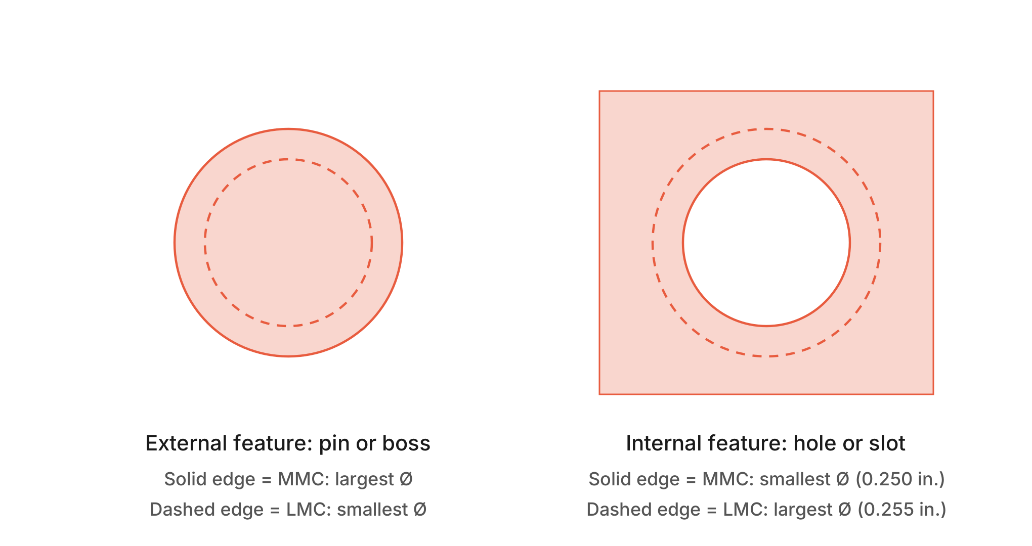
Every feature of size has two size limits. Maximum material condition (MMC) is the limit at which the feature contains the most material, and least material condition (LMC) is the limit at which it contains the least.

For an external feature such as a pin or boss, MMC is the largest diameter and LMC is the smallest. For an internal feature such as a hole or slot, it is reversed: MMC is the smallest diameter and LMC is the largest. A hole dimensioned Ø0.250 +0.005/−0.000 has an MMC of 0.250 in. and an LMC of 0.255 in.

:::html
<figure class="my-6 mx-auto max-w-sm">
  <img
    src="/images/insights/understanding-gdt-tolerance-calculations-figure-1.png"
    alt="External pin or boss versus internal hole: MMC and LMC size limits"
    loading="lazy"
    class="w-full h-auto rounded-xl border border-stone-200"
  />
  <figcaption class="mt-3 text-sm text-stone-600 text-center">
    Example Image A
  </figcaption>
</figure>
:::

Size limits also control form. Under Rule #1 of ASME Y14.5, a regular feature of size may not extend beyond a boundary of perfect form at MMC. A pin produced at its MMC must be perfectly straight, and as it moves toward LMC it may bend or go out of round by up to the difference.

## How bonus tolerance works

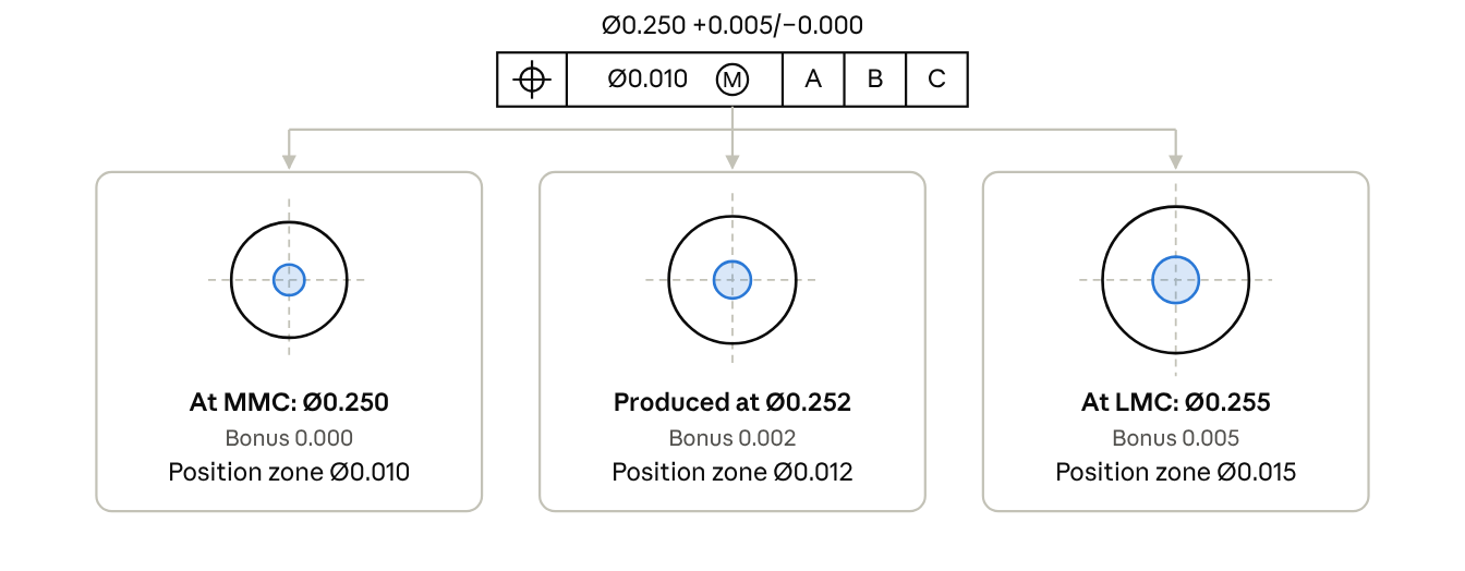
When a position tolerance is specified at MMC, the stated tolerance applies only when the feature is at MMC. As the feature departs from MMC toward LMC, the allowed tolerance increases by the amount of that departure. This additional tolerance is called bonus tolerance.

For a hole dimensioned Ø0.250 +0.005/−0.000 with a position tolerance of Ø0.010 at MMC to datums A, B and C:

:::html
<div class="overflow-x-auto my-6">
<table class="w-full text-sm border-collapse border border-stone-200">
<thead>
<tr class="bg-stone-50 text-left">
<th class="border border-stone-200 px-4 py-3 font-semibold text-stone-900">Actual hole size</th>
<th class="border border-stone-200 px-4 py-3 font-semibold text-stone-900">Departure from MMC</th>
<th class="border border-stone-200 px-4 py-3 font-semibold text-stone-900">Allowed position tolerance</th>
</tr>
</thead>
<tbody class="text-stone-700">
<tr>
<td class="border border-stone-200 px-4 py-3 align-top">0.250 (MMC)</td>
<td class="border border-stone-200 px-4 py-3 align-top">0.000</td>
<td class="border border-stone-200 px-4 py-3 align-top">Ø0.010</td>
</tr>
<tr>
<td class="border border-stone-200 px-4 py-3 align-top">0.252</td>
<td class="border border-stone-200 px-4 py-3 align-top">0.002</td>
<td class="border border-stone-200 px-4 py-3 align-top">Ø0.012</td>
</tr>
<tr>
<td class="border border-stone-200 px-4 py-3 align-top">0.255 (LMC)</td>
<td class="border border-stone-200 px-4 py-3 align-top">0.005</td>
<td class="border border-stone-200 px-4 py-3 align-top">Ø0.015</td>
</tr>
</tbody>
</table>
</div>
:::

:::html
<figure class="my-6 mx-auto max-w-2xl">
  <img
    src="/images/insights/understanding-gdt-tolerance-calculations-figure-2.png"
    alt="Position tolerance at MMC with bonus tolerance at three produced hole sizes"
    loading="lazy"
    class="w-full h-auto rounded-xl border border-stone-200"
  />
  <figcaption class="mt-3 text-sm text-stone-600 text-center">
    Example Image B
  </figcaption>
</figure>
:::

The callout on the drawing does not change. As the produced hole moves from its MMC of 0.250 toward its LMC of 0.255, the position tolerance zone grows by the same amount.

A larger hole leaves more room around the mating pin or fastener, so its location can vary further without affecting assembly.

If no modifier is shown, the tolerance applies regardless of feature size (RFS), which is the default under Rule #2, and no bonus is available. A tolerance specified at LMC works in the opposite direction, with the bonus increasing as the feature moves toward MMC. LMC is generally used when the concern is protecting material, such as a minimum wall or edge distance, rather than assembly.

## How to calculate the MMB and LMB

ASME Y14.5 uses maximum material boundary (MMB) for a boundary on or outside the material of a feature, and least material boundary (LMB) for a boundary on or inside it. For a feature specified at MMC, the two worst-case boundaries are called the virtual condition and the resultant condition.

The virtual condition is the boundary on the mating side. It combines the feature's MMC with the geometric tolerance and stays constant at every produced size, because any change in size is offset by an equal amount of bonus. It is used for fit and clearance, and it is the size of a functional gauge pin.

The resultant condition is the worst-case boundary on the material side. It combines the feature's LMC with the geometric tolerance and the full bonus available at LMC. It is used for minimum wall thickness and edge distance.

:::html
<div class="overflow-x-auto my-6">
<table class="w-full text-sm border-collapse border border-stone-200">
<thead>
<tr class="bg-stone-50 text-left">
<th class="border border-stone-200 px-4 py-3 font-semibold text-stone-900">Feature</th>
<th class="border border-stone-200 px-4 py-3 font-semibold text-stone-900">Virtual condition (MMB)</th>
<th class="border border-stone-200 px-4 py-3 font-semibold text-stone-900">Resultant condition (LMB side)</th>
</tr>
</thead>
<tbody class="text-stone-700">
<tr>
<td class="border border-stone-200 px-4 py-3 align-top">External (pin, boss)</td>
<td class="border border-stone-200 px-4 py-3 align-top">MMC + geometric tolerance</td>
<td class="border border-stone-200 px-4 py-3 align-top">LMC − geometric tolerance − bonus at LMC</td>
</tr>
<tr>
<td class="border border-stone-200 px-4 py-3 align-top">Internal (hole, slot)</td>
<td class="border border-stone-200 px-4 py-3 align-top">MMC − geometric tolerance</td>
<td class="border border-stone-200 px-4 py-3 align-top">LMC + geometric tolerance + bonus at LMC</td>
</tr>
</tbody>
</table>
</div>
:::

For the hole in this article, the virtual condition is 0.250 − 0.010 = 0.240, and the resultant condition is 0.255 + 0.010 + 0.005 = 0.270. For a pin dimensioned Ø0.375 +0.000/−0.003 with position Ø0.005 at MMC, the virtual condition is 0.375 + 0.005 = 0.380, and the resultant condition is 0.372 − 0.005 − 0.003 = 0.364.

## Example: worst-case minimum wall thickness

A bracket has two holes located 1.000 apart by a basic dimension. Each hole is Ø0.250 +0.005/−0.000 with a position tolerance of Ø0.010 at MMC to datums A, B and C. Because both holes reference the same datum reference frame, their true positions are defined relative to a common reference. However, each hole's actual axis can vary within its permitted position tolerance zone. The worst-case wall thickness must account for both holes reaching their respective limiting positions.

To find the thinnest the wall between the holes can be:

- Identify the boundary on the material side. The wall is between the holes, so the calculation uses each hole's resultant condition, 0.270.
- Locate the boundary. The resultant condition boundary is centered on the hole's true position, so each hole can remove material up to 0.135 from its basic location.
- Subtract both from the basic distance: 1.000 − 0.135 − 0.135 = 0.730.

The thickest the wall can be comes from the virtual condition instead: 1.000 − 0.120 − 0.120 = 0.760. On any conforming part, the wall measures between 0.730 and 0.760, even though the nominal geometry shows 0.750.

If the design requires a minimum wall of 0.735, this callout does not guarantee it. Changing the position tolerance to Ø0.010 at LMC would make the outer boundary a constant 0.265 and raise the minimum wall to 0.735. The trade-off is on the assembly side, where the inner boundary of a hole produced at MMC drops to 0.235.

## Why tolerance calculations matter for first article inspection

AS9102 requires a first article inspection report to account for every design characteristic on the drawing. On Form 3, each characteristic is listed with its drawing location, its requirement and the actual measured result. For a position tolerance at MMC, the requirement depends on the measured size of the feature, so the result can only be evaluated correctly if the bonus is applied.

For example, a hole measured at Ø0.253 with a position of Ø0.012 conforms. Its departure of 0.003 from MMC raises the allowed tolerance to Ø0.013. Compared against the Ø0.010 in the feature control frame alone, the same hole would be reported as nonconforming.

A functional gauge made at the virtual condition confirms that the holes will assemble, but it does not give a position value, and it does not check the resultant condition boundary that controls wall thickness.

Common issues when reporting these characteristics include:

- The position result is compared against the feature control frame value without the bonus earned at the measured size
- Bonus is applied to a tolerance specified RFS, where no bonus is allowed
- MMC and LMC are reversed for an internal feature, so the bonus is calculated in the wrong direction
- The bonus is calculated from the nominal size instead of the measured size

Recording the measured size next to the position result makes the bonus traceable, so the customer can see why a position value larger than the feature control frame value was accepted.

## How GroundControl supports this

GroundControl's [FAI Generation Tool](https://gndctl.com/solutions/first-article-inspection-software) builds the AS9102 report from the drawing, listing each characteristic with its requirement on Form 3, including geometric tolerances such as position at MMC. For customers receiving FAIRs from their suppliers, [FAIR Review](https://gndctl.com/solutions/quality-reporting-software) lets the quality team review each report on the platform and return questions to the supplier.

:::html
<div class="mt-6">
  <a
    href="https://cal.com/team/groundcontrol/demo"
    data-cta="book_demo"
    data-cta-location="gdt_tolerance_calculations_article"
    class="resources-cta-button font-display inline-flex items-center justify-center gap-2 rounded-full bg-coral-500 px-6 py-3 text-base font-medium text-white transition-colors hover:bg-coral-600"
  >
    Book a demo
    <svg class="h-4 w-4" fill="none" stroke="currentColor" viewBox="0 0 24 24" aria-hidden="true">
      <path stroke-linecap="round" stroke-linejoin="round" stroke-width="2" d="M17 8l4 4m0 0l-4 4m4-4H3" />
    </svg>
  </a>
</div>
:::

## FAQ

### What is the difference between the MMB and the LMB?

The maximum material boundary is on or outside the material of a feature, and the least material boundary is on or inside it. For a feature specified at MMC, the virtual condition is used for fit and clearance, and the resultant condition is used for minimum wall thickness and edge distance.

### Does the virtual condition change with feature size?

No, not when the tolerance is specified at MMC. Any increase in hole size adds an equal amount of bonus to the position tolerance, so the boundary on the mating side stays the same. This is why a functional gauge can be built to a single size.

### What happens if no material condition modifier is shown?

The tolerance applies regardless of feature size (RFS), and no bonus is allowed. The worst-case boundaries still exist but come from the fixed tolerance alone. For the hole in this article at Ø0.010 RFS, the inner boundary is 0.240 and the outer boundary is 0.265.

### Why does bonus tolerance matter for first article inspection?

AS9102 requires each characteristic on Form 3 to have a requirement and a measured result. For a position tolerance at MMC, the requirement depends on the measured size, so a result compared against the feature control frame value alone can show a conforming feature as nonconforming.

---

Full site index: https://gndctl.com/llms.txt